Hinge Joint
The Hinge Joint restricts translation and two additional angular degrees of freedom, so the body can only rotate around one defined axis. This joint is useful for representing doors or wheels rotating around an axis. The user can specify limits and motor settings for the hinge.
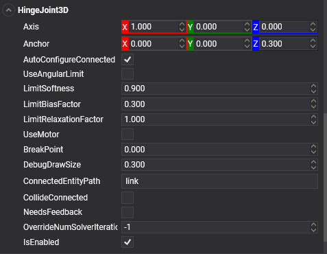
HingeJoint3D
In Evergine, a Hinge Joint is implemented using the HingeJoint3D component.
Common Properties
| Property | Default | Description |
|---|---|---|
| ConnectedEntityPath | null | The entity path of the connected body. Only when the path is valid is a joint established properly. |
| Axis | 1, 0, 0 | The direction of the axis around which the body swings. The direction is defined in local space. |
| Anchor | 0, 0, 0 | The position of the axis around which the body swings. The position is defined in local space. |
| AutoConfigureConnected | true | Enable this setting to automatically calculate the ConnectedAnchor position and ConnectedAxis to match the global position of the anchor property. This is the default setting. Disable it to configure the position of the connected anchor and connected axis manually. |
| ConnectedAxis | auto-calculated | The joint axis relative to the connected body. |
| ConnectedAnchor | auto-calculated | Manually configure the connected anchor position in the connected body's local space. |
| BreakPoint | 0 | If the value is greater than 0, it indicates the force that needs to be applied for this joint to break. |
| CollideConnected | false | Determines whether a collision between the two bodies managed by the joint is enabled. |
Limit Properties
The following properties set the limits of the rotation movement.
| Property | Default | Description |
|---|---|---|
| UseAngularLimit | false | If enabled, the angle of the hinge will be restricted within the LowerAngularLimit and UpperAngularLimit values. |
| LowerAngularLimit | 0 | The lowest angle the rotation can go. |
| UpperAngularLimit | 0 | The highest angle the rotation can go. |
| LimitSoftness | 0.9 | Once an angle is greater than softness * the maximum angle, the constraint begins to take effect. Lowering the value of softness softens the constraint boundaries. |
| LimitBiasFactor | 0.3 | The rate at which the constraint corrects errors in orientation. A value of 1 will ensure that the constraint is always obeyed. It is recommended to keep bias between 0.2 and 0.5. |
| LimitRelaxationFactor | 1 | The rate at which the angular velocity is changed by the constraint. A low value means the constraint will modify the velocities slowly, leaving the boundaries appearing softer. |
Motor Properties
The following properties set the motor properties of the joint.
| Property | Default | Description |
|---|---|---|
| UseMotor | false | If enabled, the motor makes the object spin around. |
| MotorTargetVelocity | 0 | The speed the object tries to attain. |
| MotorTargetImpulse | 0 | The impulse applied in order to attain the speed. |
Using Hinge Joint
This snippet creates a small bridge of a series of connected bodies.
protected override void CreateScene()
{
    this.Managers.RenderManager.DebugLines = true;

    // Load your material
    var cubeMaterial = this.Managers.AssetSceneManager.Load<Material>(DefaultResourcesIDs.DefaultMaterialID);

    int chainLength = 6;
    Entity previousLink = null;

    var size = new Vector3(0.5f, 0.1f, 2);
    var separation = 0.6f;

    // Create the chain...
    for (int i = 0; i < chainLength; i++)
    {
        // The first object is kinematic (we don't want a falling chain :D)
        var rigidObjectType = (i == 0) ? RigidBodyType3D.Kinematic : RigidBodyType3D.Dynamic;

        // Create the link entities...
        var link = this.CreateCube(cubeMaterial, new Vector3(i * separation, 0, 0), size, rigidObjectType);

        if (previousLink != null)
        {
            // Add a PointToPoint joint to the previous link connected to the current link...
            previousLink.AddComponent(new HingeJoint3D()
            {
                ConnectedEntityPath = link.EntityPath,
                Axis = Vector3.Forward,                     // Sets the hinge axis to Z
                Anchor = new Vector3(separation / 2, 0, 0)  // Sets the Anchor between the source and connected body
            });
        }

        previousLink = link;

        this.Managers.EntityManager.Add(link);
    }
}

private Entity CreateCube(Material material, Vector3 position, Vector3 size, RigidBodyType3D rigidBodyType)
{
    Entity cube = new Entity()
        .AddComponent(new Transform3D()
        {
            Position = position,
            Scale = size
        })
        .AddComponent(new MaterialComponent() { Material = material })
        .AddComponent(new CubeMesh())
        .AddComponent(new MeshRenderer())

        .AddComponent(new RigidBody3D()         // Add a RigidBody3D component...
        {
            PhysicBodyType = rigidBodyType
        })
        .AddComponent(new BoxCollider3D());     // Add a BoxCollider3D to the physic body...

    return cube;
}
Add Motor
At the end of the previous CreateScene() method, add the following code:
var firstHinge = this.Managers.EntityManager.FindFirstComponentOfType<HingeJoint3D>();
firstHinge.UseMotor = true;
firstHinge.MotorTargetVelocity = 4;
firstHinge.MotorTargetImpulse = 100;
This will produce the following effect: